![]()
another
approach to wind
Vertical-axis turbines may avoid the limitations of today's standard propeller-like machines.
The
image of modern wind turbines has finally crept into the public consciousness.
At long last, the Dutch windmill and the Great Plains wind-powered water
pump have been supplanted by something sleek and futuristic: a tower that
is 10, 20, even 30 stories tall with a rotor comprising two or three thin
blades.
But the image does not fully account for the reality. Anyone not directly
involved in the wind turbine industry might be forgiven for thinking that
all wind turbines face into the wind, with a horizontal axis of rotation.
But there is another, less familiar, type of wind turbine, with a vertical
axis. It has origins going back much farther in history than the common
propeller-type, horizontal-axis turbines.
Horizontal-axis wind turbine technology is likely to peak in the next
few years, largely because of the limitations of the blades and their
effects on the machine. The power output of a wind turbine is directly
related to the swept area of its blades. The larger the diameter, the
more power it is capable of extracting from the wind. The larger the blades,
the stronger they need to be to withstand the higher levels of centrifugal
force and stresses caused by their additional size and weight. The extra
mass for strength adds further to the structure's weight and so
compounds the problem.
Furthermore, the bending moments across the swept area of the blade can
vary considerably, with a possible difference of several meters a second
in wind speeds between the top and the bottom of the blade's rotation.
This all adds up to a substantial increase in fatigue, not only in the
blade structure, but also in the machine's hub, bearing, driveshaft,
and support tower. With a 31-meter (100-foot) blade weighing around 4.5
tons and a 54-meter (177-foot) blade weighing about 13 tons, the weight
of the blade for a horizontal-axis turbine is not proportional to the
size and power rating of the machine.
Along
the Vertical Axis
I believe that horizontal-axis machines will prove unable to meet the
growing demand for larger, more cost-effective wind turbines—particularly
with the recent trend to build on more costly, but more productive sites
offshore. We need to look back in history and concentrate on further developing
the simpler vertical-axis designs. Without the same structural limitations,
vertical-axis turbines can be produced much larger and so take advantage
of significant economies of scale.
Vertical-axis windmills are not some futuristic concept. There is evidence
of their existence dating back as far as the seventh century B.C. However,
all the different designs can be categorized into two basic principles—pushed
by the wind or pulled by the wind. The push principle is the oldest by
far, originally consisting of two or more vertical sails or paddles that
are blown around their vertical axis by the wind. A Persian vertical-axis
design dating from about 200 B.C. channeled the wind with walls towards
the paddles of the machine, which were then pushed around by the wind.
Finnish engineer S.J. Savonius substantially updated this basic concept
in 1922, when he replaced the sails with cups or half oil drums with their
open sides opposing each other and fixed to a central vertical shaft.
The cup in line with the wind flow catches the wind and so turns the shaft
180 degrees, bringing the opposing cup into the flow. This cup then repeats
the process, causing the shaft to rotate a further 180 degrees and complete
a full rotation. There have been numerous variations on the same theme,
some with additional cups or drums on the same shaft and some with their
cups or drums set at different angles or positions on the shaft.
 |
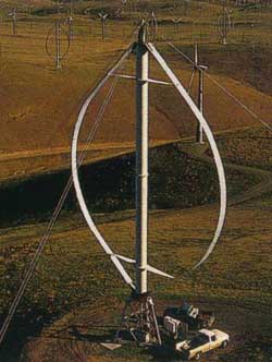
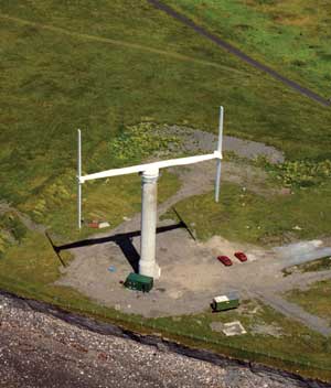
| The VAWT 450 (above), built in Wales by VAWT Ltd., had a total swept area of 450 square meters. The blade and cross arm were mounted on the top of a 40- meter concrete tower, and it produced 130 kw. It was disassembled in 2000. |
In recent years, this principle has undergone further significant development,
noticeably by two Finnish companies, Shield Oy and Windside Production
Ltd. Both of these companies produce small helical or fluted bladed machines,
where the drums of the Savonius rotor have evolved into spiral-formed
vanes. These machines are ideal for use on buoys, offshore platforms,
buildings, signs, and posts, where small amounts of power are required.
They are often used to charge battery backup systems or to supplement
low-voltage photovoltaic solar panels, used to power signs, public telephones,
low-voltage transmitters, and other small systems.
These devices benefit from being extremely rugged, quiet, and omnidirectional.
They are more efficient than the conventional Savonius machine and exert
less stress on their support structures. There are ambitions to scale
up these types of machines to megawatt size, but research and development
funding for vertical-axis turbines is scarce.
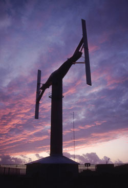
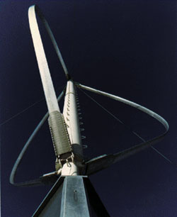
The other option, using the pull principle, shows more promise. In 1931,
a French engineer, George J. M. Darrieus, invented a new type of vertical-axis
wind turbine. The Darrieus type of machine consists of two or more flexible
airfoil blades, which are attached to both the top and bottom of a rotating
vertical shaft, giving the machine the appearance of a giant egg whisk.
The wind blowing over the airfoil contours of the blade create aerodynamic
lift, which actually pulls along the blades.
Although nowhere near as much research has been carried out on these types
of machines as on horizontal-axis turbines, both the United States and
Canada had large research programs working on the Darrieus design in the
1970s and '80s. This work culminated with the building of a 4.2
MW machine called Eole C in Cap Chat, Quebec.
There were also a number of commercial wind farms built in the United
States using the Darrieus machine design, most of which were built by
a company called The FloWind Corp. On the whole, the machines proved to
be quite efficient and reliable.
However, there was a problem with fatigue on the blades, which were designed
to flex, thus allowing for the extra centrifugal forces in high winds
and at high rotation speeds.
Unfortunately, this flexing led to premature fatigue of the blade material,
and led to a number of blade failures. Furthermore, the bottom fixing
of the blade is only a few feet above ground level. While this makes the
generating plant easily accessible, the machines cannot take advantage
of the higher wind speeds that a tall support tower offers.
Varying
the Geometry
Some researchers began to look at improving the Darrieus machine by rationalizing
the geometry of the blades. One such group, led by Peter Musgrove at Reading
University in England, hit upon straightening out the blades of a Darrieus-type
wind turbine. The hope was that this would overcome the blade fatigue
problem and improve performance. But at the time, it was believed that
the simplest solution—an H-shape blade configuration—could
over-speed and become dangerously unstable under excessively windy conditions.
To avoid this, Musgrove proposed that a reefing mechanism be incorporated
in the machine's design, thus allowing the blades to be feathered
in high winds. These earlier machines with feathering blades were known
as "variable geometry" vertical-axis wind turbines.
There were a number of such designs, which had different ways of feathering
their blades. During the late 1970s, English research, which included
wind tunnel tests and the building of a few prototype machines in the
40 kW to 100 kW range, culminated in a final design: a reefing arrowhead
blade for a large 25-meter, 130 kW-rated machine. The machine, known as
the VAWT 450, was built at Carmarthen Bay in South Wales and was funded
by the U.K. Department of Trade and Industry.
 |
 |
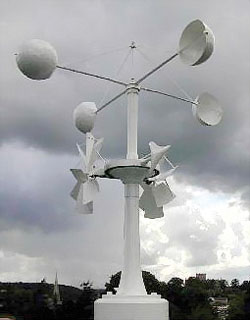
| No single design for vertical-axis wind turbines has emerged as optimal. This has led to an explosion of innovation—from anemometer-type turbines (top) and Darrieus machines (above and below) to some highly unconventional designs. |
 |
The research carried out on the VAWT 450 established that the elaborate
mechanisms used to feather the blades were unnecessary. Instead, the drag/stall
effect created by a blade leaving the wind flow would limit the speed
at which a connected blade in the wind flow could move forward. This led
the way to a fixed straight-bladed design—the H-rotor.
The developer of the Model 450, VAWT Ltd., went on to build a larger straight-bladed
machine at Carmarthen Bay, called the VAWT 850, which had a rated power
output of 500 kW. The VAWT 850 was extensively tested and proved that
the simplicity of the basic H-blade configuration was practical.
The machine was not without its problems. Extremely high levels of torque
created by the rotation of the blades led to the failure of the power
transmission arrangement on several occasions. The machine's main
generating plant was housed in the center of the support tower and the
blades' rotation was transferred via gearboxes and a torque tube.
The high stresses exerted on the torque tube caused it to fail and proved
difficult to overcome.
The catastrophic failure of the main bearing, coupled with the withdrawal
of government research funding, signed the machine's death warrant.
The VAWT 450 and VAWT 850 machines at Carmarthen Bay were both demolished
at the turn of the century, in accordance with the original plan.
Advances in horizontal-axis turbines in Europe have slowed of late, and
governments and industry have begun to reassess the promise of vertical-axis
designs. Several vertical-axis designs are currently available, among
them a number of build-it-yourself kits for conventional Savonius rotor
wind turbines. Mostly designed around two halves of an oil drum, these
are all small machines and are used mainly for battery charging or for
irrigation pumping.
The two Finnish companies, Shield Oy and Windside Production, produce
the fluted type of Savonius machine. The machines are simple, rugged,
and reliable, but at present come only with outputs up to 25 kW. They
are ideal for isolated areas with severe weather, in applications such
as sign or buoy lighting, telecommunications, and backup power supply.
Both companies plan to expand their range of machines and develop the
principle into megawatt scale devices.
Radically
Different Machines
There are at least two new research and development programs into the
design of Darrieus machines, planned in the United States and Canada.
These new machines will use the latest composite materials to maximize
the fatigue resistance of their blades and prolong the overall useful
life of the machine.
The Canadian Chinook 2000, manufactured by Sustainable Energy Technologies,
is the only large Darrieus type of machine currently in production, to
my knowledge. It is rated at 250 kW and the manufacturer claims that it
can be erected in remote areas without the use of a crane.
The H-rotor design has not disappeared, either. There are two companies
currently producing H-rotor type turbines— Heidelberg Motor GmbH
of Germany and Solwind Ltd. of New Zealand. Both companies offer a range
of machines rated up to 300 kW. The machines use a low-speed magnetic
levitation alternator, which means that the turbines have only one moving
part, making them extremely quiet and reliable.
There are numerous patents issued for all sorts of variations of vertical-axis
turbines, but the only radically different machines to reach the market
are the Turby wind turbine from the Netherlands and the Ropatec from Italy.
The Turby machine is designed to be used in the built environment, on
posts, roofs of buildings, fixed to walls, etc. It uses an all-in-one
bearing hub/alternator, has a peak output of 3 kW, and is rated at 2.5
kW. The Ropatec hybrid design is a mix of H-rotor and Savonius. These
machines are very robust and are suitable for isolated mountainous regions
or for offshore platforms.
Eurowind Developments Ltd. is planning to introduce a modular turbine
that will have power outputs ranging from 1 MW to more than 10 MW. The
concept combines the most up-to-date but proven wind turbine, shipbuilding,
and construction technology. The modular design is intended for a number
of applications, ranging from offshore to various land installations,
in wind farms or standing alone.
 |
| H-rotor wind turbines were tested at Carmarthen Bay in Wales. A model with a similar blade arrangement may one day generate up to 10 MW and reuse abandoned industrial chimneys as platforms. |
The machine can be mounted on certain types of industrial structures,
such as chimneys and other similar tall structures, without inhibiting
their normal use. Rather than having a wind turbine that exerts a specific
load onto its support tower, Eurowind's modular system is designed
to tailor the wind turbine—and, therefore, its load—to the known
reserve strength of the host structure. The interface between structure
and turbine would then absorb the most significant stress loads produced
by the rotation of the machine's blades, to prevent excessive stressing
of the structure.
When built, the machine will be the world's first megawatt-class,
H-rotor, vertical-axis turbine and will be the only modularly constructed
wind turbine. These features will enable machines of varying proportions
and power outputs to be assembled using standardized components, with
a considerable cost savings.
Tall masonry structures of the sort that are suitable for the Eurowind
turbines were once a common sight in industrial cities and towns across
the globe. However, as technology changed, many of these structures became
obsolete. Indeed, the structures have lent their name to an entire subset
of old-fashioned, low-tech businesses: smokestack industries.
With luck, we will soon be able to turn that sobriquet on its head. Smokestacks
(and other remnants of the industrial past) will provide clean, green,
and efficient energy by sprouting high-tech devices capable of wringing
energy from the flowing wind.
Steven Peace is Executive Director of Eurowind Developments
Ltd.
in Newhaven, England. He is also an associate member of the Institute
of Energy, as well as a consultant member of the
International Committee on Industrial Chimneys.
![]()
home | features | news update | marketplace | departments | about ME | back issues | ASME | site search
© 2004 by The American Society of Mechanical Engineers